

AHU Cooling Coil Selection Guide: Water Coil, DX Coil, Rows, Fins & Condensate
Key fact: AHU cooling coil selection must be specified from a complete data set – entering air condition, leaving air target, airflow, coil medium (chilled water or refrigerant), face velocity, rows, fin spacing, circuiting, pressure drop and condensate management. A coil is not a single capacity number; it is the heat exchanger that links the AHU, the duct system, the chilled water plant or the DX refrigeration circuit.

Scope: this page is an air-to-fluid heat-exchanger selection guide. It focuses on entering/leaving air, water or refrigerant conditions, face velocity, rows, fin pitch, circuiting, pressure drop, condensate carry-over and drain design. It does not repeat whole-AHU selection or the existing DX air-handler RFQ workflow.
Key fact: AHU cooling coil selection must be specified from a complete data set – entering air condition, leaving air target, airflow, coil medium (chilled water or refrigerant), face velocity, rows, fin spacing, circuiting, pressure drop and condensate management. A coil is not a single capacity number; it is the heat exchanger that links the AHU, the duct system, the chilled water plant or the DX refrigeration circuit.
Practical rule: the buyer’s biggest risk is hidden mismatch. A coil with sufficient nominal capacity still fails when face velocity is too high (condensate carry-over into the duct), when water flow is wrong (under-performance), when drain design is weak (water damage and mold), or when a DX circuit is not coordinated with the AHU casing, TXV/EEV control and refrigerant safety basis under ISO 5149.
This guide supports buyers comparing SongXin’s air handling unit supplier, modular AHU selection guide, direct expansion air handler selection guide, DX unit vs chilled water system and AHU filter selection guide resources.
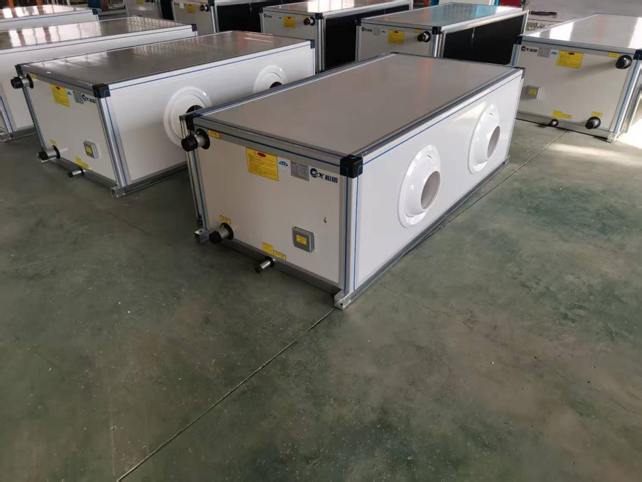
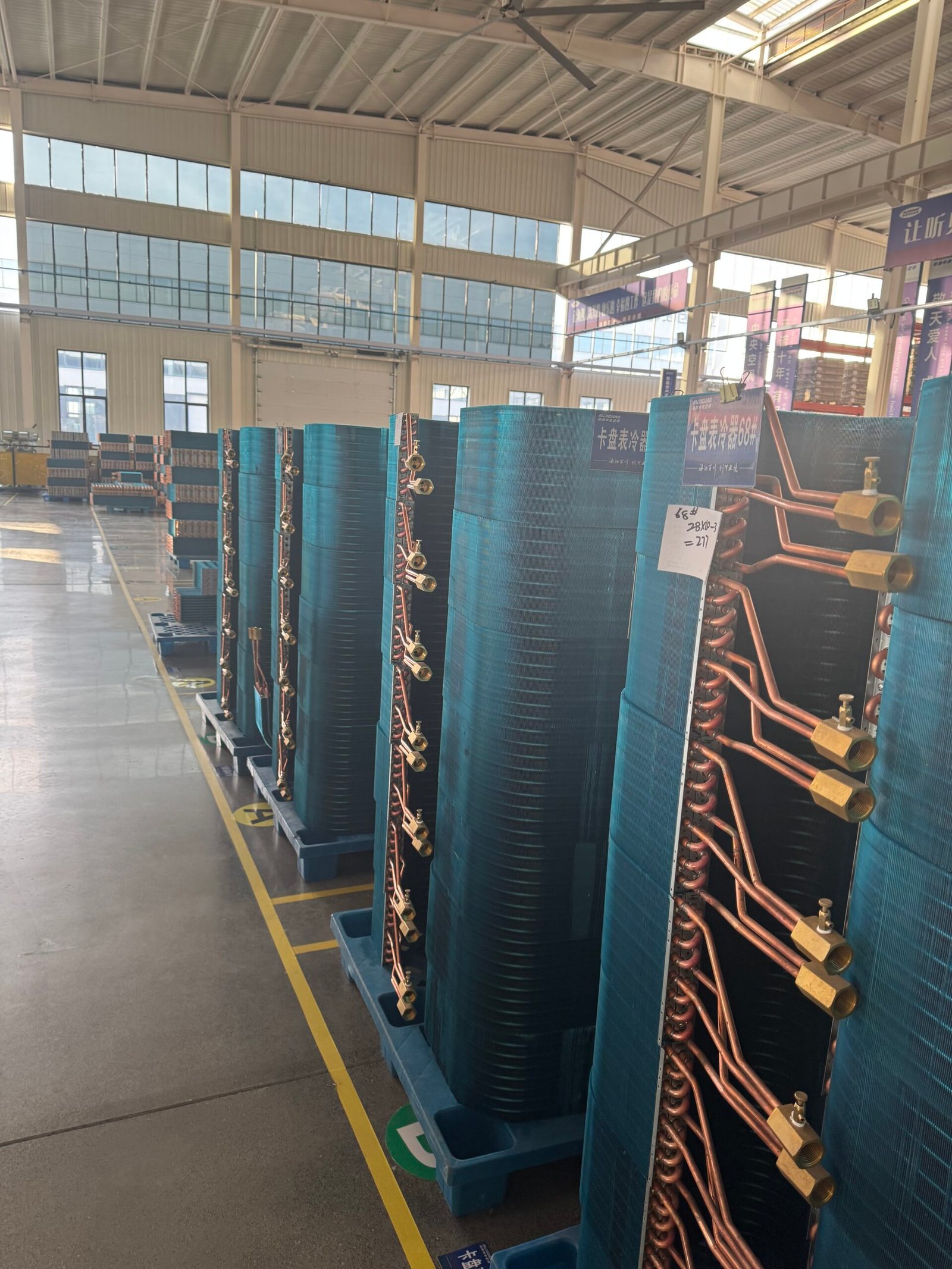
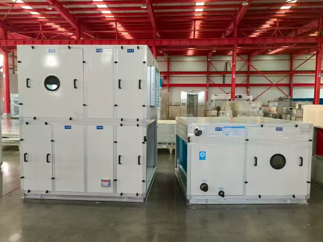
AHU Cooling Coil Selection: What Buyers Must Specify
Specify the entering and leaving air conditions, airflow, required total and sensible cooling duty, design pressure-drop budget, fluid type and the permitted space for the coil. Decide between a chilled-water coil and a direct-expansion (DX) evaporator only after the upstream cooling source and control strategy have been defined. Face velocity, row count, fin spacing and circuiting are outcomes of an engineered heat-exchanger selection—not universal specifications for a climate or building type.
| Required design input | What the buyer should provide |
|---|---|
| Airflow and entering state | Design m³/h plus dry-bulb and humidity (wet-bulb, RH with barometric pressure, or humidity ratio) |
| Leaving air / loads | Target leaving dry-bulb and humidity, total load, sensible load and latent or humidity requirement |
| Chilled-water system | Entering and leaving water temperatures, approved flow range, fluid/glycol concentration and water-side pressure-drop limit |
| DX refrigeration circuit | Matched outdoor condensing unit, refrigerant designation, expansion control, operating envelope, circuiting and refrigerant safety assessment |
| AHU constraints | Available coil face and depth, allowable clean/wet/dirty pressure drops, fan capability, filter position and maintenance/pull space |
| Hygiene and condensate | Wet-coil moisture carryover limit, cleanable drain pan, trap design pressure and project material/corrosion requirements |
Buyer decision: ask the supplier for a model-specific coil-selection printout showing total/sensible capacity and leaving-air state at the same design point as the RFQ, plus air- and fluid-side pressure drops. Do not approve a quotation based only on a generic number of rows or a nominal kW rating.
Chilled-Water Cooling Coil vs DX Evaporator Coil
Both types cool and dehumidify air, but a water coil is connected to a chilled-water distribution system, while a DX coil must be matched to a compressor/condensing-unit refrigeration circuit. Neither option has universally better latent control or inherently lower service cost: performance depends on coil temperatures, controls and part-load operation.
| Selection item | Chilled-water AHU coil | DX evaporator coil |
|---|---|---|
| Upstream source | Central chiller plant, district cooling or other chilled-water supply | Matched compressor and condenser assembly |
| RFQ water/refrigerant inputs | Water temperatures, flow, fluid properties, fouling and allowable pressure drop | Refrigerant, saturation conditions, expansion device, refrigerant distribution and matching condensing-unit data |
| Controls | Water-valve/pump and supply-air / humidity control sequence as designed | Compressor staging or modulation plus TXV/EEV and humidity/freeze protections where applicable |
| Capacity / dehumidification | Calculate from psychrometrics and the selected water flow and temperatures | Calculate from psychrometrics with the full refrigerant-side operating envelope |
| Safety / jurisdiction | Water/glycol mechanical and freeze-protection requirements | Refrigerant charge, leakage, occupied-space safety and A2L/A3 precautions as applicable to refrigerant and local code |
| Testing and documentation | Coil thermal rating and air/water pressure-drop data | Coil rating if within standard scope plus matched system performance, circuit/control documentation |
AHRI 410-2023 specifies rating methods for covered forced-circulation air-cooling and heating coils. Not every DX or heat-pump coil falls within its scope: the standard excludes certain capillary/restrictor-controlled DX coils, flooded coils, microchannel and heat-pump refrigerant coils. EN 13053 concerns the AHU and components; neither standard reference proves a specific SongXin model is certified.
Five Coil-Selection Variables That Determine Actual Performance
1. Face velocity and wet-coil carryover
Approximate coil face velocity is air volume flow (m³/h) ÷ [3,600 × free-face area (m²)]; the manufacturer’s net face-area definition should be used consistently. ASHRAE’s Air-Cooling and Dehumidifying Coils chapter notes that comfort dehumidifying coils are frequently selected around 400–500 fpm (about 2.0–2.5 m/s). This is a common design range, not a universal carryover threshold or guarantee. Carryover also depends on condensate rate, coil geometry, fin wetting, air distribution, casing, eliminator and drain design. Obtain the coil supplier’s maximum approved wet-face velocity.
2. Rows and coil depth
Increasing coil rows can raise heat-transfer surface but also changes wet/dry pressure drop, approach temperature, cost and cleaning access. A four-, six- or eight-row count is not sufficient evidence that the selected coil will achieve a specified sensible heat ratio. Require software-rated total and sensible capacity at the stated design point, leaving-air humidity and fan duty.
3. Fin spacing and cleaning access
Fin density should be stated unambiguously: FPI = 25.4 ÷ fin pitch in mm; for example, 2.1 mm pitch is about 12.1 fins per inch. Dense fins may improve surface density but generally increase fouling sensitivity and pressure drop. A cleanroom or hospital application does not automatically imply a special fin density or upstream HEPA filter; select filtration and cleanability for the actual hygiene specification.
4. Water or refrigerant circuiting
Water-coil circuits are selected to maintain acceptable tube-side velocities, pressure drop and heat transfer at minimum and maximum water flow. A higher number of passes does not universally reduce pressure drop. For DX, specify refrigerant distributor layout, circuit staging, oil return, TXV/EEV control and matching of compressor and coil. Interlaced versus face-split circuiting has trade-offs, so obtain part-load performance and freeze-protection information for the actual assembly.
5. Tube/fin materials and protective treatments
Typical choices include copper tube/aluminium fin, coated aluminium fins and other materials when supported by the manufacturer’s product range. Coastal distance alone cannot establish a corrosion grade or guarantee the durability of a particular coating. Ask for environmental exposure, cleaning chemicals, compatible coating process, maintainability and any applicable test evidence.
| Selection parameter | Document needed before ordering |
|---|---|
| Air-side capacity | Airflow, entering/leaving psychrometric state, total and sensible coil kW |
| Wet/dry fan loading | Coil air-pressure-drop values plus filters, casing and duct system pressure budgets |
| Water/refrigerant circuit | Water flow and pressure drop, or verified matching condensing-unit/expansion/refrigerant circuit data |
| Coil construction | Face dimensions, rows, fin pitch, tube material, treatments, drainage/access drawings |
| Actual operating envelope | Full- and part-load selection results; dehumidification/carryover and freeze/charge safeguards when relevant |
Worked Example A: Chilled-Water Coil for a 20,000 m³/h AHU
Hypothetical calculation, not a real SongXin hotel project or a manufacturer coil rating. Consider an AHU supplying 20,000 m³/h. For quick screening assume air density of 1.20 kg/m³, an independently determined entering-to-leaving moist-air enthalpy difference of 26.8 kJ/kg, and 6°C supply / 12°C return chilled water. An actual calculation must obtain entering and target leaving air enthalpies and humidity ratios from measured or designed psychrometric states (dry-bulb, wet-bulb/RH and site pressure).
| Screening calculation | Illustrative output |
|---|---|
| Air mass flow ≈ 20,000 ÷ 3,600 × 1.20 | 6.67 kg/s (using assumed density) |
| Total duty ≈ air mass flow × assumed enthalpy change | 6.67 × 26.8 ≈ 179 kW, subject to correct moist-air enthalpy and dry-air mass-flow basis |
| Coil face area ≈ 20,000 ÷ (3,600 × 2.3) | 2.42 m² if 2.3 m/s is the provisional selected velocity |
| Chilled-water flow ≈ 179 ÷ (1.163 × 6) | 25.7 m³/h for pure-water approximation at 6 K temperature rise |
| Wet-coil rows, fins and circuiting | To be determined by software rated capacity, sensible/latent split, pressure drops and manufacturer design |
Do not derive a fixed six-row minimum or assume 30–35 kW per row from these arithmetic checks. Request selected-model wet-coil air-pressure drop, entering and leaving air states, water pressure drop, actual face dimensions and drain arrangement. Verify that water and air-side total capacities agree on a consistent thermodynamic basis.
Condensate volume must come from the humidity-ratio change
The idealized moisture-removal rate is dry-air mass flow × (entering humidity ratio − leaving humidity ratio). Do not claim a condensate mass in kg/h without a psychrometric calculation and a drain-system design allowance. Check any bypass factor, re-evaporation, variable outdoor-air fraction and part-load conditions in the actual equipment selection.
For a detailed RFQ, provide ambient climate, entering/leaving air psychrometric conditions, fan and filter pressure budgets, 6/12°C water design and any glycol content. Ask for the actual coil model and its air/water-side selection printout.
Worked Example B: DX Coil and Refrigerant Safety for an 8,000 m³/h Retail AHU
Hypothetical air-side illustration: suppose an air handler delivers 8,000 m³/h at a provisional density of 1.20 kg/m³. If a properly calculated entering-to-leaving air enthalpy difference were 22 kJ/kg, the preliminary total duty would be about 58.7 kW. This is not a statement that any specific DX refrigerant circuit or SongXin model provides that capacity.
| Selection check | Calculation / required evidence |
|---|---|
| Nominal air mass flow | 8,000 ÷ 3,600 × 1.20 ≈ 2.67 kg/s |
| Hypothetical air-side load | 2.67 × 22 ≈ 58.7 kW; replace assumed Δh with the project psychrometric result |
| Illustrative face area | 8,000 ÷ (3,600 × 2.4) ≈ 0.93 m² if a wet-coil velocity of 2.4 m/s is provisionally examined |
| Refrigeration package | Manufacturer-confirmed refrigerant, compatible condensing unit, expansion device, superheat/subcooling targets and operating envelope |
| Coil construction | Manufacturer rating for row/fin/circuit design, wet pressure drop, sensible/latent output and condensate handling |
R32 and other mildly flammable refrigerants are project-specific safety decisions
R32 is classified A2L (lower-flammability class). Never infer an acceptable refrigerant charge, occupied-space compliance or a required detector solely from cooling capacity. Charge limits and risk-mitigation measures depend on the exact equipment configuration, occupied room volume, installation height and type, refrigerant distribution/leak scenario, product standard and the locally applicable code. Use the manufacturer’s safety assessment and the applicable version of ISO 5149, IEC 60335-2-40 and jurisdiction-specific rules as relevant. No allowable-charge value or product certification is asserted for this illustrative example.
For an international B2B tender, request the matched indoor/outdoor model numbers, control sequence, approved refrigerant piping lengths and elevations, leakage mitigation arrangement where required, and final signed technical data before ordering.
Condensate Drainage: Design from Actual AHU Pressure and Moisture Load
A dehumidifying coil requires a cleanable sloped condensate pan, a properly sized drain connection and trap, and insulation appropriate to the surrounding dew-point conditions. Pooling, carryover and improperly trapped drainage can lead to water damage and microbial growth; neither a universal pan slope nor a universal DN25 pipe size is guaranteed to work in every AHU.
| Design element | What to verify |
|---|---|
| Drain pan | Corrosion-resistant material compatible with the project, no stagnant zones, cleanability, accessible drain, correctly approved slope and downstream catch length |
| Expected drainage | Use the calculated dry-air mass flow and entering/leaving humidity ratios, with a stated safety allowance for transient operation |
| Draw-through / negative-pressure trap | Measure negative static pressure at the pan relative to the discharge point; size the trap seal, inlet leg and free drainage per AHU manufacturer’s installation detail |
| Blow-through / positive-pressure trap | Use the actual positive pan pressure and manufacturer drawing; prevent unwanted air leakage and drainage backflow |
| Pipe diameter and slope | Check condensate flow, trap geometry, vent location, available fall, freeze risk and local plumbing requirements |
| Commissioning | Demonstrate free drainage at design fan operation and with appropriate startup/shutdown conditions, then verify service access |
Pressure-unit example: −750 Pa at a negative-pressure drain pan corresponds to about 76 mm water column (750 ÷ 9.81). This figure is the pressure equivalent, not a complete trap-design height; inlet leg, seal depth, outlet leg and venting must all follow the manufacturer’s arrangement. Do not apply a fixed “2 × pressure” trap rule or a mandatory downstream vent independent of the installed configuration.
Where hygiene, hospital or pharmaceutical requirements apply, verify the project’s approved drain-pan material, cleanability, inspection requirements and relevant local guidance rather than assuming one stainless grade is universally mandatory.
Coil Materials and Corrosion Protection by Actual Exposure
Corrosion and hygiene requirements depend on chloride deposition, washdown chemicals, industrial contaminants, relative humidity, cleaning procedures and expected maintenance—not simply the number of kilometres from the shoreline. Copper/aluminium coils may be suitable for many indoor comfort applications, but a coating or alternative material should be justified through supplier data and the project’s exposure assessment.
| Project exposure | Engineering selection considerations |
|---|---|
| Ordinary filtered indoor return air | Evaluate standard tube/fin assembly, condensate wetting, filter maintenance and coil cleaning |
| Coastal or salt-laden air | Specify actual chloride/corrosivity conditions, compatible fin/tube/coating options, coating coverage and maintenance procedure |
| Industrial chemical exposure | Identify contaminants and cleaning solvents; request corrosion compatibility evidence for tubes, fins, casing and drain pan |
| Food, healthcare or cleanroom duties | Project hygiene/cleanability standard, inaccessible crevices, drain design, disinfection and material approvals where applicable |
| Outdoor-air-heavy AHU | Check wet-operation duration, filtration, frost protection, coil access and any special treatment |
Ask for material identification and coating specifications on the actual coil model. Never infer a material’s price premium, useful life or universal anti-corrosion performance from a generic table; these require vendor quotations and test records.
Common AHU Cooling Coil Mistakes and How to Avoid Them
| Common mistake | Procurement correction |
|---|---|
| Using an absolute 2.5 m/s moisture-carryover threshold | Request manufacturer’s tested or documented maximum approved wet-coil face velocity for the selected geometry and condensate rate |
| Choosing four, six or eight rows only from climate labels | Compare leaving air condition, actual total/sensible capacity, fan duty and coil cost from selected-model data |
| Fixing a universal air-pressure-drop value per row | Use rated clean/dry and operating wet pressure drop for the actual rows, fins and airflow |
| Using generic refrigerant charge from cooling kW | Have the equipment supplier assess the actual refrigerant charge, room/installation geometry and code compliance |
| Using a single standard 150-mm P-trap | Size and commission the pan/trap to the actual local static pressure and manufacturer arrangement |
| Ignoring air/filter and water/refrigerant controls | Confirm the full AHU air-system resistance, valve/EEV/condensing-unit control and low-load behavior |
| Asserting model certification without a record | Request a current certificate or test report that matches the proposed model and the intended certification scope |
The product purchase decision is based on the complete engineered assembly, not an isolated catalogue statement. See the AHU product overview and request a project-specific model selection with the appropriate drawings and documents.
AHU Cooling Coil RFQ Checklist: What Suppliers Must Document
Information to send with your inquiry
Design airflow (m³/h); outdoor-air percentage; entering air dry-bulb and wet-bulb/RH with altitude; leaving air design dry-bulb and moisture target; sensible and total coil kW; chilled-water fluid and temperatures/flow or verified matched DX condensing-unit and refrigerant details; casing space; clean and wet pressure-drop budgets; corrosion/cleaning requirements; condensate management and destination country.
What the supplier must return before technical approval
| Submittal item | Required response |
|---|---|
| Exact model and geometry | Coil face area, rows, fin pitch, tube layout, circuiting and maintenance/pull space |
| Rated coil performance | Total and sensible kW at the actual entering and leaving air states; selected air velocity and humidity change |
| Water or refrigerant operating point | Water temperature/flow/pressure-drop output, or matched DX refrigerant circuit controls and operating envelope |
| Fan / hydraulic matching | Wet/dry coil pressure drop, relevant filter and casing resistances, pump/fan duty and minimum flow |
| Moisture control and maintenance | Wet-coil carryover review, condensate pan/trap arrangement, corrosion treatment and cleaning access |
| Testing and compliance | Only the standards actually in scope; model-specific evidence of test results and current certifications/declarations where required |
| Commercial details | Factory documentation, drawing revision, lead time, spares, warranty and Incoterms scope for the destination |
Acceptance rule: the proposed coil must demonstrate the specified leaving-air and moisture duty at the design point with acceptable system pressure drops and safe, maintainable drainage. AHRI 410, EN 13053 and Eurovent are references with different scopes and must not be treated as automatic certifications.
Compare the SongXin AHU product page and use the dedicated WhatsApp inquiry below to send air-side and medium-side design data without a website form.
Frequently Asked Questions About AHU Cooling Coils
What face velocity should I use for an AHU cooling coil?
For many comfort dehumidifying coils, approximately 2.0–2.5 m/s (400–500 fpm) is a common starting range described by ASHRAE. It is not a universal lower or upper limit. The final velocity must meet the selected coil’s approved wet-coil carryover, capacity and pressure-drop criteria.
How many rows does a chilled-water cooling coil need?
There is no universal four-, six- or eight-row rule. Rows, face dimensions, circuiting, fin pitch and water flow must be chosen together from the required total/sensible capacity, entering/leaving air and water conditions, and allowable pressure drops.
How is fin pitch converted to FPI?
Fins per inch (FPI) equals 25.4 divided by fin pitch in millimetres. Thus 2.1 mm is about 12.1 FPI. The right density depends on heat-transfer area, fouling, pressure drop and cleaning access.
When should an AHU use a water coil rather than a DX coil?
A water coil is natural where a suitable chilled-water source is available. A DX coil requires a refrigerant circuit matched to the compressor, expansion control and condenser. Compare actual controls, air-side duty, lifecycle service and applicable refrigerant safety provisions.
Is a wet-coil drift eliminator always mandatory above 2.5 m/s?
No universal rule applies across all designs. Ask the specific coil/air-handler supplier for wet-face carryover limits and any eliminator design requirement; these depend on coil construction, condensate rate and air distribution.
How should drain pans and traps be sized?
Use the expected condensate rate, drain-pan configuration and the actual static pressure at the pan. A pressure in pascals can be converted to an equivalent water column by dividing by about 9.81 Pa/mm. Full trap geometry, pipe diameter and venting follow the manufacturer’s arrangement and local requirements, not a universal one-size-fits-all drawing.
Can I assume an R32 charge is safe because the coil is under 60 kW?
No. R32 is A2L and requires evaluation of actual refrigerant charge, installation location, occupied-space conditions, product-standard requirements and local code. Cooling duty alone cannot establish allowable charge or detector requirements.
Does AHRI 410 certification apply to every DX coil?
No. AHRI 410-2023 has specific scope exclusions, including some capillary/restrictor-controlled DX evaporators, flooded evaporators, heat-pump refrigerant coils and microchannel coils. Ask whether the specific selected coil is in scope and whether its model has any independently verified certification.
What data belongs in an AHU cooling coil RFQ?
Send airflow; entering and leaving air conditions; total/sensible duty; coil medium; water or refrigerant circuit data; wet/dry air pressure-drop budgets; available coil dimensions; cleaning, corrosion and condensate specifications; electrical/control interface and any project-specific compliance needs.
Editorial and Technical Basis
Updated October 9, 2026. This article explains coil-selection methods using published industry references and explicitly labeled hypothetical arithmetic. It is not a record of an actual SongXin customer project or certified coil test. Performance, 100% factory test claims, available materials and product certification must be confirmed from the current specific-model submittals. No independent engineer’s project approval is represented by this page.
Sources
- AHRI Standard 410-2023, “Performance Rating of Forced-Circulation Air-Cooling and Air-Heating Coils”, https://www.ahrinet.org/search-standards/ahri-410-performance-rating-forced-circulation-air-cooling-and-air-heating-coils
- European Commission policy reference for EN 14511 air-conditioner / chiller / heat-pump rating conditions, https://webgate.ec.europa.eu/single-market-compliance-space/notified-bodies/notified-body/standards/standard/3474
- BS EN 13053:2019, “Ventilation for buildings – Air handling units – Rating and performance for units, components and sections”, https://knowledge.bsigroup.com/products/ventilation-for-buildings-air-handling-units-rating-and-performance-for-units-components-and-sections-1
- Eurovent Certification – ECP-AHU programme, https://www.eurovent-certification.com/en/cms/news/programme-focus-air-handling-units-ahus
- ASHRAE Handbook – Fundamentals (psychrometrics chapter), https://www.ashrae.org/technical-resources/ashrae-handbook
- ISO 5149-1:2014, “Refrigerating systems and heat pumps – Safety and environmental requirements – Part 1: Definitions, classification and selection criteria” (including A2L refrigerant indoor charge guidance), https://www.iso.org/standard/54979.html
- SongXin HVAC, “Air Handling Unit” (commercial AHU product overview; model-specific coil configurations, tests and compliance require separate confirmation), https://sxinhvac.com/products/terminal-units/air-handling-unit/
- SongXin HVAC, “Quality Control & Testing”, https://sxinhvac.com/company/quality-control-testing/
- Capital Coil & Air, “Guidelines for Air Velocities” – manufacturer-oriented discussion of face velocity; not a universal wet-coil carryover limit, https://www.capitalcoil.com/guidelines-air-velocities/
- Trane Engineers Newsletter Live, “HVAC Coil Selection and Optimization” – face velocity and moisture carry-over guidance, https://www.trane.com/content/dam/Trane/Commercial/global/products-systems/education-training/continuing-education-gbci-aia-pdh/HVAC-Coil-Selection-and-Optimization/APP-CMC054-EN_course%20material.pdf
- Historical ANSI/ASHRAE Standard 62.1-2001 Addendum t, discussing condensate drainage provisions; check the currently adopted code and actual manufacturer’s trap drawing, https://www.ashrae.org/file%20library/technical%20resources/standards%20and%20guidelines/standards%20addenda/62-2001/62-2001_addendum-t.pdf