

Airport HVAC Plant Room Design: Chillers, AHUs, Pumps and Redundancy
An airport HVAC plant room should be designed around continuity, maintenance access and load diversity, not only equipment capacity.
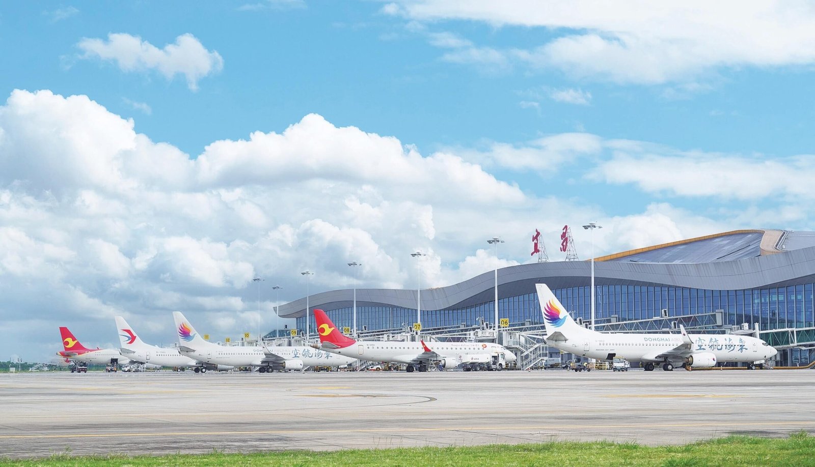
An airport HVAC plant room should be designed around continuity, maintenance access and load diversity, not only equipment capacity. Terminals, baggage areas, security zones, lounges, offices, retail areas and boarding gates all have different schedules, but they depend on the same cooling and air-side infrastructure that runs 20+ hours per day, 365 days a year.
The practical rule is direct: choose the plant-room layout that lets the airport maintain cooling while one major component is offline. For most terminal projects, that means clear chiller staging, standby pump logic, AHU service access, BMS alarms and a maintenance route that does not interrupt passenger operations.
This guide complements SongXin’s airport HVAC system design guide, airport HVAC maintenance checklist, air-cooled screw chiller (150–1,475 kW range), water-cooled chiller supplier and air handling unit (1,000–40,000 m³/h, 12–610 kW) pages.

Quick Answer for Buyers
An airport HVAC plant room should include staged cooling production, standby pumping, maintainable AHUs, filter access, safe electrical clearance, fire/smoke integration and BMS alarm visibility. For medium and large terminals, a single full-size chiller or single pump is a weak design because one fault affects many passenger zones.
Start selection with peak cooling load, operating schedule, number of zones, outdoor design condition, fire/smoke strategy and redundancy requirement. Then decide whether air-cooled screw chillers, water-cooled chillers, modular AHUs, process AHUs or DX units fit the actual terminal layout. The right plant room is the one that keeps passenger-facing areas operating during maintenance and integrates correctly with the airport’s life-safety systems.
Airport Size Classification and Cooling Load Range
Airport HVAC plant size scales with passenger throughput, gross floor area and climate. These are typical planning ranges – confirm with project load calculation.
| Airport size | Annual passengers | Terminal GFA | Typical peak cooling load | Plant room footprint |
|---|---|---|---|---|
| Regional / small | < 1 million pax/yr | 5,000 – 15,000 m² | 600 – 2,500 kW (170 – 700 RT) | 80 – 250 m² |
| Medium domestic | 1 – 5 million pax/yr | 15,000 – 50,000 m² | 2,500 – 8,000 kW (700 – 2,300 RT) | 250 – 700 m² |
| Large international | 5 – 25 million pax/yr | 50,000 – 250,000 m² | 8,000 – 35,000 kW (2,300 – 10,000 RT) | 700 – 2,500 m² |
| Major hub | 25 – 100 million pax/yr | 250,000 – 800,000 m² | 35,000 – 120,000 kW (10,000 – 34,000 RT) | 2,500 – 8,000 m² + multiple plants |
| Mega hub (top 10) | > 100 million pax/yr | > 800,000 m² | > 120,000 kW (> 34,000 RT) | distributed plant strategy |
Reference benchmarks:
- Dubai DXB (87 mppa): central + distributed chilled water plants > 100,000 RT total
- Singapore Changi (multi-terminal): district cooling supply
- Beijing Daxing (PKX): central plant + thermal storage; ~120,000+ kW peak
- Hong Kong HKIA: seawater-cooled district cooling
- London Heathrow T2/T5: water-cooled chiller plants with thermal storage
The plant room is a system, not a collection of machines. A chiller with correct capacity still fails the airport if pumps, valves, filters, fire dampers or BMS alarms are not coordinated.
Airport Plant Room Equipment Map
An airport plant room links cooling production, water distribution, air treatment, fire/smoke control and BMS monitoring. Each part should have a defined failure response.
| Plant-room element | Main duty | Airport risk | Selection rule |
|---|---|---|---|
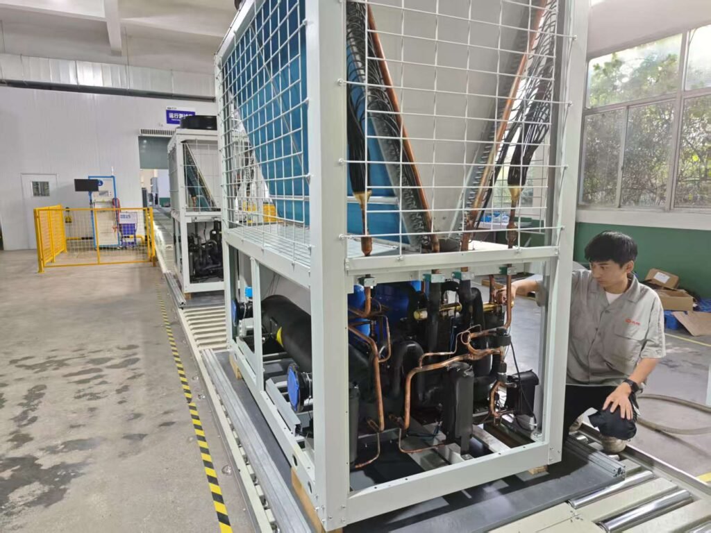
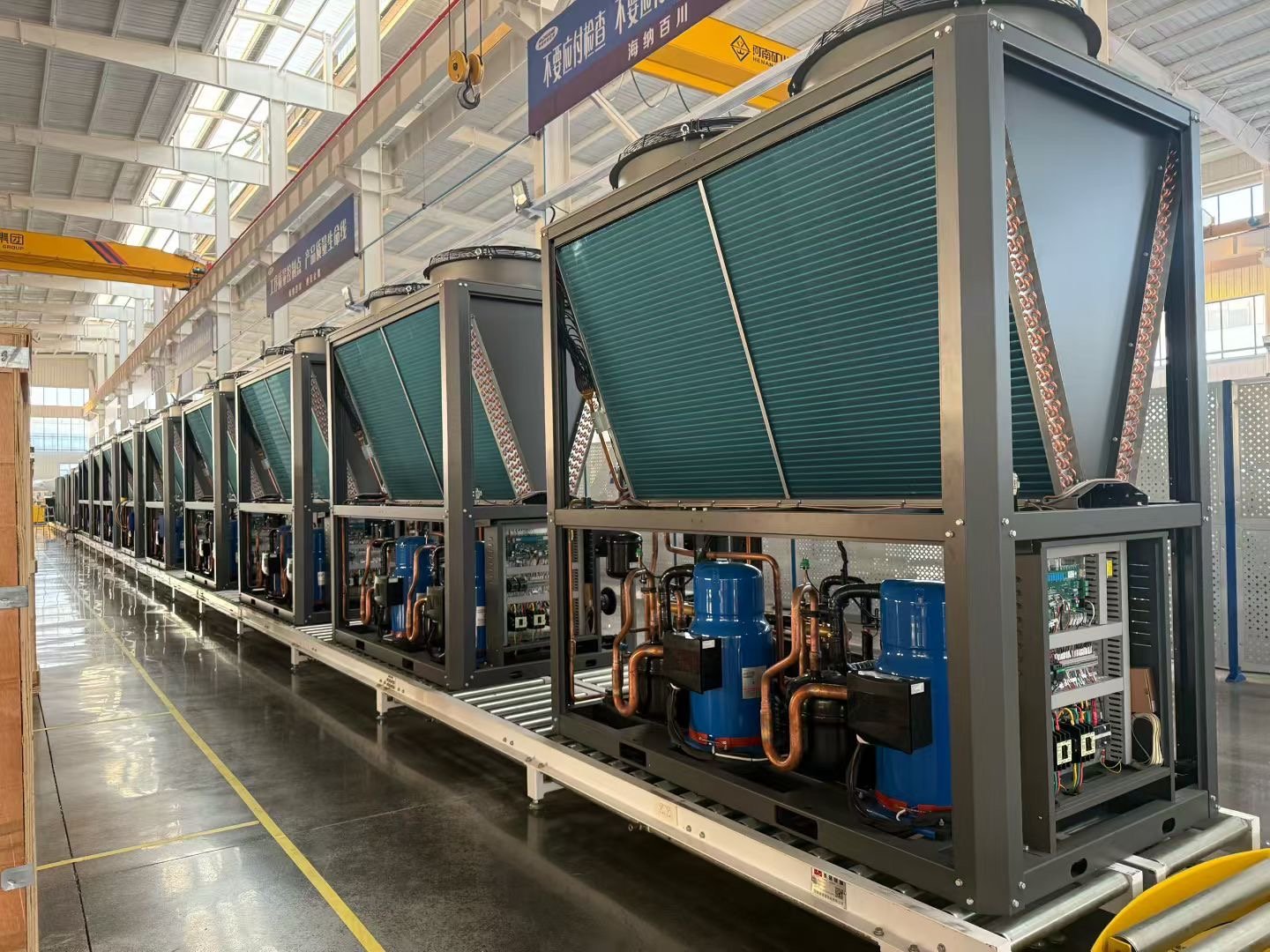
| Air-cooled screw chiller | Produces chilled water without cooling tower | Outdoor ambient derating | Rate capacity at local design ambient. SongXin: 150–1,475 kW, -35 to +48 °C[9] |
| Water-cooled chiller | Produces chilled water with condenser water loop | Tower + water-treatment complexity | Use when tower infrastructure + skilled team exist |
| Cooling tower | Rejects condenser water heat | Drift, Legionella, freeze | Variable-speed fans + treatment |
| Chilled water pumps | Move water to AHUs and FCUs | One pump fault affects many zones | Duty/standby or N+1 logic |
| Condenser water pumps | Move water to cooling tower | Pump failure → chiller trip | Always N+1 |
| Thermal storage tank (optional) | Stores chilled water for peak shaving | Stratification & insulation | Used in mega hubs for peak shifting |
| AHUs (terminal / lounge / office) | Treat air for terminal zones | Filter & coil access disrupts service | Service clearance + access panels. SongXin: up to 40,000 m³/h, 610 kW per unit[10] |
| Smoke / fire dampers | Compartmentalize during fire | False trip → cooling loss | Annual NFPA 80 / 92 testing |
| BMS and alarms | Monitor plant, zones and faults | Hidden faults grow into terminal complaints | Critical-point alarming + SCADA |
| Standby power (gen + ATS) | Maintain critical cooling during outage | Long restart on chillers | Quick-restart sequence required |
Plant Room Location Strategy
The plant room can be placed in different locations. Each option has trade-offs.
| Location | Pros | Cons | Typical use |
|---|---|---|---|
| Basement / lower level | Quiet, hidden, central piping route | Flood risk, drainage, ventilation cost | Large international terminals |
| Rooftop (air-cooled chiller) | No plant room needed for chiller; short refrigerant lines | Roof load, ambient exposure, hail/dust | Small-medium airports, terminal extensions |
| External standalone plant building | Easy expansion, low fire risk to terminal | Long water piping run | Mega hubs (central energy plant) |
| District cooling supply (off-site) | No on-site chiller; airport buys chilled water | Vendor dependency, contract cost | Singapore Changi, HK HKIA, Dubai DXB districts |
| Distributed (per-pier plant rooms) | Reduces single-point failure; shorter pumping | More duplicate equipment, higher CAPEX | Multi-pier terminal layouts |
Practical rule: for terminals > 80,000 m² GFA, a distributed plant strategy (2+ plant rooms feeding zones) reduces single-point failure and shortens chilled water pump head. For < 30,000 m² GFA, a single plant is usually more economic.
Redundancy and Load Diversity
Airport HVAC redundancy should be based on the areas that must remain operational during equipment failure. A departure hall, security checkpoint or control room deserves stronger backup than a storage room.
| Area type | Cooling priority | Redundancy approach | Acceptable outage |
|---|---|---|---|
| ATC tower / control rooms | Critical (Tier IV equivalent) | N+2, dedicated DX backup, UPS-fed controls | 0 min (always available) |
| Security checkpoints / immigration | Critical | N+1 + standby pump | < 5 min |
| Server / IT / network rooms | Critical | Precision DX + chilled water + N+1 | < 1 min |
| Departure / arrival halls | High | Staged chillers + standby pumps | < 30 min |
| Boarding gates, jet bridges | High | Zonal AHU staging | < 60 min |
| Retail and lounges | Medium | Zonal AHU staging | 1–4 hr acceptable |
| Offices and staff areas | Medium | Shared plant with zone control | 4 hr acceptable |
| Baggage handling areas | Medium | Shared plant capacity | 4 hr acceptable |
| Storage and back-of-house | Lower | Shared plant capacity | 8 hr acceptable |
Load diversity matters because airport zones do not peak at the same time. Departure halls peak during boarding, retail during peak shopping hours, baggage during turnover. A central plant uses staging to match load changes, reducing wasted compressor runtime. Typical airport diversity factor: 0.65–0.80 (peak plant ≈ 65–80% of sum of zone peaks).
Worked Example: Chiller Staging for 8,000 kW Terminal
A simple staging example helps the procurement team compare different chiller configurations. Assume a medium international airport terminal has 8,000 kW peak cooling load, designed for N+1 redundancy at peak, with 5,000 hours/year average operation.
Option A: One 8,000 kW chiller
| Metric | Value |
|---|---|
| Installed capacity | 8,000 kW |
| Available during one-unit outage | 0 kW |
| Largest single point of failure | Catastrophic |
| Part-load efficiency | Poor below 30% load |
| Verdict | Unacceptable for any airport |
Option B: Two × 4,000 kW chillers (N redundancy)
| Metric | Value |
|---|---|
| Installed capacity | 8,000 kW |
| Available during one-unit outage | 4,000 kW (50%) |
| Part-load efficiency | Poor below 25% per chiller |
| Verdict | Limited acceptance: Acceptable for small/medium airports only |
Option C: Three × 4,000 kW chillers (N+1)
| Metric | Value |
|---|---|
| Installed capacity | 12,000 kW |
| Available during one-unit outage | 8,000 kW (100%) |
| Staging flexibility | 3 stages: 33% / 66% / 100% |
| Part-load efficiency | Better (one chiller at full load + others off) |
| Verdict | Recommended for medium international terminal |
Option D: Four × 2,700 kW chillers + N+1
| Metric | Value |
|---|---|
| Installed capacity | 10,800 kW |
| Available during one-unit outage | 8,100 kW |
| Staging flexibility | 4 stages: 25% / 50% / 75% / 100% |
| Part-load efficiency | Best (smaller machines run efficiently at low load) |
| Verdict | Best-fit: Recommended for large international hub |
Recommendation
For an 8,000 kW airport terminal:
- Small/medium: Option C (3 × 4,000 kW) – simpler, lower CAPEX
- Large international: Option D (4 × 2,700 kW) – better part-load efficiency, finer staging, smaller single-unit footprint
In a recent SongXin RFQ review for an 8,000 kW terminal plant in Southeast Asia, the engineering team rejected the single-chiller concept because the one-unit outage capacity was 0 kW and recommended Option D for the climate’s wide-load profile (cool nights at 60% load, hot afternoons at 95% load).
Plant Room Footprint Estimation
| Component | Footprint per unit | Typical clearance |
|---|---|---|
| Air-cooled screw chiller (1,000 kW) | ~12–18 m² outdoor pad | 2 m all sides + 3 m fan discharge |
| Water-cooled chiller (1,000 kW) | ~8–12 m² indoor | Tube-pull = 1.5 × chiller length |
| Chilled water pump (50–200 m³/h) | ~2–3 m² each | 1 m access |
| Cooling tower (1,000 kW heat rejection) | ~8–15 m² outdoor | 3 m intake clearance |
| AHU (20,000 m³/h, 200 kW) | ~10–18 m² | 1.5 m service + filter pull |
| Electrical panel (per chiller) | ~3–5 m² | 1.2 m working clearance (NEC/IEC) |
Quick estimate (medium international terminal, 8,000 kW load):
| Element | Footprint |
|---|---|
| 4 chillers @ 2,700 kW (Option D) | 4 × 25 = 100 m² (water-cooled) |
| Cooling tower yard | 80 m² |
| Pump room (8 pumps) | 40 m² |
| Electrical room | 60 m² |
| Maintenance / spares | 50 m² |
| Aisles + clearances | 70 m² |
| Total plant room | ~400 m² |
| Distributed AHU rooms (10 × 40 m²) | 400 m² distributed |
For a large hub at 35,000 kW, expect 1,500–2,500 m² central plant + multiple distributed AHU rooms.
Plant Room Layout and Service Matrix
The plant room layout should protect maintenance access over the equipment life. A compact plant room that saves construction space creates expensive service work later.
| Design item | Minimum planning value | Airport reason | Service interval |
|---|---|---|---|
| Chiller service clearance | Manufacturer clearance + tube-pull path (1.5× chiller length) | Tube cleaning, compressor removal | Major inspection every 6-12 months |
| Pump access | Clear access to motor, coupling, strainer, drain | Pump faults affect many zones | Monthly visual + vibration check |
| AHU filter access | Full filter removal path | Terminal dust loads filters quickly | Every 1-3 months |
| Drain pan access | Visible cleaning and slope route | Blocked drains create water leakage | Every 3-6 months |
| Electrical panels | NEC 110.26 / IEC 60364 clearance | Lockout and maintenance safety | Annual inspection |
| Lifting / monorail provision | Over chiller and AHU | Component replacement | Per major overhaul |
| Floor drain + bund | Around chiller + pump areas | Refrigerant / oil / water spill | Per ISO 5149-1 |
The mechanism is maintenance delay. When the service route is blocked, routine tasks take longer, filters stay dirty, coils transfer less heat, and passenger-zone complaints rise.
Fire and Smoke Integration
Airport HVAC plant rooms must integrate with terminal fire and smoke control. This is often poorly coordinated in design.
| Fire/smoke element | Integration requirement |
|---|---|
| Smoke control mode | HVAC supply/return fans switch to pressurize/exhaust per zone strategy |
| Fire dampers | NFPA 80; auto-close on fire signal; access for annual test |
| Smoke dampers | NFPA 92; modulating control by zone smoke detector |
| Stairwell pressurization fans | Often shared with HVAC mechanical room |
| Atrium smoke exhaust | Coordinated with terminal HVAC fan controls |
| Refrigerant leak detection | ISO 5149-1 mandatory in machine rooms; alarm + ventilation interlock |
| Generator / standby | ATS transfer < 10s for critical loads; chiller restart sequence < 90s |
Reference standards: NFPA 90A (Air Conditioning and Ventilating Systems), NFPA 92 (Smoke Control), local airport fire code (FAA AC 150/5210, EASA, ICAO Annex 14).
Energy and Sustainability Targets
Modern airports target specific HVAC energy benchmarks:
| Metric | Typical target | Best-in-class |
|---|---|---|
| Chilled water plant kW/RT | 0.65 – 0.85 (full load) | < 0.55 |
| Chilled water plant kW/RT (IPLV, annual) | 0.45 – 0.60 | < 0.40 |
| Chiller IPLV | 6.0 – 7.5 | > 8.0 |
| AHU SFP (specific fan power) | 1.5 – 2.5 kW/(m³/s) | < 1.2 |
| Total HVAC energy / terminal area | 80 – 150 kWh/m²·yr | < 60 |
| Renewable energy contribution | 15 – 30% | > 50% (solar + thermal storage) |
ASHRAE 90.1 provides baseline energy compliance. LEED, BREEAM and EDGE offer certification routes. For specific airport energy guidance, Airport Carbon Accreditation, owned and governed by ACI EUROPE in cooperation with ACI regions and ACI World, defines staged carbon-management certification levels.[8]
RFQ Data and Specification Checklist
An airport HVAC plant room RFQ should define load, redundancy and service access before equipment price comparison.
RFQ input list
- Airport area type: terminal, concourse, baggage, office, control room, ATC, hotel.
- Peak cooling load in kW or RT and load profile by zone.
- Required redundancy: N, N+1, N+2, duty/standby or owner-defined outage case.
- Outdoor design temperature and chilled water supply/return temperatures (typical 6/12 °C or 7/13 °C).
- AHU airflow, ESP, filtration class and fresh-air ratio (ASHRAE 62.1 minimum 7.5 L/s/person).
- Pump head, water flow, piping route and control valve strategy.
- Plant-room layout, equipment access path and lifting limitation.
- BMS alarm points (typically 200–800 per plant), control sequence and maintenance reporting requirement.
- Fire/smoke control integration (NFPA 90A/92, local code).
- Energy targets (ASHRAE 90.1 / LEED / BREEAM / Airport Carbon Accreditation (ACI EUROPE)).
- Standby power capacity and chiller restart sequence.
Specification checklist
| Item | Minimum answer before purchase |
|---|---|
| Chiller duty | Capacity at project ambient and leaving-water temperature |
| Chiller IPLV | Confirmed IPLV value per AHRI 550/590 |
| Pump duty | Flow, head, standby logic, strainer access |
| AHU duty | Airflow, ESP, coil, filter, drain, sound details |
| Redundancy | Available capacity during largest-unit outage |
| Fire integration | NFPA 90A/92 + smoke damper + leak detector |
| Controls | BMS points, alarms, staging, trend data, SCADA integration |
| Standards | ISO 9001, CE/AHRI/ASHRAE; airport-specific tender annexes |
| Documents | Datasheet, wiring diagram, O&M manual, commissioning checklist, spare-parts list |
For airport projects, ask SongXin to compare air-cooled screw chiller, water-cooled chiller, AHU and DX support equipment under the same load and redundancy basis.
Common Mistakes
The first mistake is treating an airport plant room like a normal commercial plant. Passenger flow, security areas and flight schedules create continuity requirements ordinary office buildings do not have.
The second mistake is selecting one large machine to reduce first cost. The worked example shows that one 8,000 kW chiller leaves 0 kW available during its own outage.
The third mistake is hiding maintenance access. Airports operate 20+ hours/day, so filter, pump and electrical service routes must be planned before the plant room is built.
The fourth mistake is ignoring BMS alarms. A chiller or pump fault that is not visible to the facilities team becomes a terminal temperature complaint before maintenance reacts.
The fifth mistake is leaving fire/smoke integration to a separate consultant. HVAC fans, dampers, controls and refrigerant leak detection must be co-designed with the life-safety strategy from day 1.
The sixth mistake is forgetting tube-pull clearance. Water-cooled chillers need 1.5× length clear at one end for tube cleaning every 2–3 years. Skipping this turns a 4-hour tube clean into a 2-day demolition job.
The seventh mistake is single-source standby power. Standby genset failure during a chiller outage = full HVAC loss. Critical airports use dual generators with auto-paralleling.
FAQ
What is an airport HVAC plant room?
An airport HVAC plant room is the mechanical area that houses or coordinates chillers, pumps, AHUs, valves, controls, fire/smoke dampers and service access for terminal cooling and ventilation. Its purpose is not only capacity production. It must support passenger comfort, equipment redundancy, maintenance safety, fire/smoke compartmentalization and BMS visibility during long operating hours.
How big is an airport HVAC plant room?
Plant room footprint scales with cooling load. For a regional airport (600–2,500 kW), expect 80–250 m². For a medium domestic airport (2,500–8,000 kW), expect 250–700 m². For a large international airport (8,000–35,000 kW), expect 700–2,500 m². Mega hubs typically use distributed plant strategies with multiple plant rooms.
How much redundancy does an airport HVAC plant need?
Airport HVAC redundancy should match the owner-defined outage case. For passenger-critical zones (ATC, security, server rooms, departure halls), N+1 or N+2 is standard. The plant should maintain required cooling when the largest chiller, pump or AHU section is under maintenance or fault. Typical: 3 × 50% or 4 × 33% chiller staging.
Air-cooled or water-cooled chillers for airports?
Air-cooled fits small/medium airports without tower infrastructure, water-stressed regions, or rooftop installation. Water-cooled fits large/mega hubs where higher COP (5.0+ vs 3.0+) and lower OPEX justify cooling tower, water treatment and plant room space. Most large international terminals use water-cooled with thermal storage for peak shifting.
What chilled water temperatures do airports use?
Most airports operate at 6/12 °C (6 °C supply, 12 °C return, 6 K ΔT) or 7/13 °C. Higher ΔT designs (5/15 °C, 6/16 °C) are used in modern terminals to reduce pump energy. Low-temperature designs (4/12 °C) are sometimes used for thermal storage applications.
What fire and smoke codes apply to airport HVAC?
Primary references: NFPA 90A (Standard for the Installation of Air-Conditioning and Ventilating Systems), NFPA 92 (Smoke Control Systems), ICAO Annex 14 (aerodrome safety), local civil aviation authority codes (FAA AC 150/5210, EASA), plus local building/fire codes. Refrigerant leak detection per ISO 5149-1 is mandatory in chiller machine rooms.
Why is service access so important in airport HVAC?
Service access is important because airport HVAC equipment runs for long hours and routine maintenance must happen without disrupting passenger areas. Poor access delays filter replacement, pump service, drain cleaning and electrical inspection. That delay reduces airflow, heat transfer and fault response speed across the terminal. Tube-pull clearance for water-cooled chillers (1.5× chiller length) is the most-skipped item.
What energy targets apply to airport HVAC?
Modern airports target chilled water plant kW/RT of 0.65–0.85 full load (best-in-class < 0.55), IPLV kW/RT 0.45–0.60 (best < 0.40), and total HVAC energy of 80–150 kWh/m²·yr (best < 60). Compliance frameworks: ASHRAE 90.1, LEED, BREEAM, Airport Carbon Accreditation (ACI EUROPE).
What RFQ data is needed for an airport plant room?
Send zone loads, peak load, operating schedule, redundancy target, chilled water temperatures, outdoor ambient, AHU airflow, ESP, filtration, pump head, BMS points, fire/smoke control strategy, energy target and plant-room drawings. This data lets SongXin compare chillers, AHUs and pumps under one airport operating basis.
Review Record
Technical review: SongXin HVAC Engineering Team, airport HVAC plant room selection review, 2026-08-03. SongXin has supplied chiller, AHU and DX equipment to airport, terminal-extension and aviation-support projects across the Middle East, Southeast Asia, South Asia, Africa and Latin America.
Sources
- AHRI 550/590 and AHRI 551/591, “Performance Rating of Water-Chilling and Heat Pump Water-Heating Packages,” https://www.ahrinet.org/search-standards/ahri-550590-i-p-and-551591-si-performance-rating-water-chilling-and-heat-pump-water-heating-packages
- European Commission policy reference for EN 14511-2 rating conditions, https://webgate.ec.europa.eu/single-market-compliance-space/notified-bodies/notified-body/standards/standard/3474
- ASHRAE Commissioning resources, https://www.ashrae.org/technical-resources/bookstore/commissioning
- OSHA, “Control of Hazardous Energy (Lockout/Tagout),” https://www.osha.gov/control-hazardous-energy
- ISO 5149-1:2014, “Refrigerating systems and heat pumps – Safety and environmental requirements – Part 1,” https://www.iso.org/standard/54979.html
- ISO 5149-2:2014, “Refrigerating systems and heat pumps – Safety and environmental requirements – Part 2,” https://www.iso.org/standard/54980.html
- ISO 16890-1:2016, “Air filters for general ventilation – Part 1,” https://www.iso.org/standard/57864.html
- EASA, “Airport Carbon Accreditation Programme,” https://www.easa.europa.eu/en/domains/environment/eaer/airports/net-zero-co2-emissions
- SongXin HVAC, “Air-Cooled Screw Chiller” (150–1,475 kW range, -35 to +48 °C operating range), https://sxinhvac.com/products/air-cooled-screw-chiller/
- SongXin HVAC, “Air Handling Unit” (1,000–40,000 m³/h, 12–610 kW), https://sxinhvac.com/products/terminal-units/air-handling-unit/
- ISO 817:2024, “Refrigerants – Designation and safety classification,” https://www.iso.org/standard/83452.html